| Brand: | Sine Image | Model: | YE0159 |
| Size: |
280*210mm 240*180mm Can Be Customized |
Material: | HD photographic paper / Film |
| Ratio: | 4:3 / 16:9 | Type: | Reflective/ Transmissive |
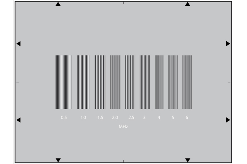
The test chart is designed for measuring horizontal static resolution. It shows vertical bars, the density variation of which gives a sinusoidal video response. This is preferred to a rectangular function test pattern, because this is in fact likely to create harmonic frequencies which can impair resolution measurement owing to know „moirés“ phenomena in CCD Camera. The bars create frequencies of 0.5, 1, 1.5, 2, 2.5, 3, 4, 5, 6MHz.
Measuring equipment: Video oscilloscope or preferably video oscilloscope with memory.
Shading correction: ON
Aperture correction: OFF
Gamma correction: OFF
Contour correction: OFF
Colour correction: OFF
Iris: F/5.6 for 2/3 '' CCD, F/4 for 1/2 '' CCD
The test chart is evenly illuminated so that for the low frequency burst at 0.5 MHz the amplitude of the video signal at the output of the correctly positioned and focussed camera is 0% (0V) for the black bars of the zebra-strip and 100% (700 mV / 75 Ohms) for the white bars of the zebra-strip.
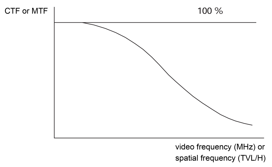
Care must be taken to avoid clipping of the signal to be measured at the black and white level. Measurements can be made on the various camera output signal, but preferably on the Y luminance signal (or coded Y with perfect B and W balance). The measurement give the contrast loss of the camera response at the value of 5 MHz, the measurement of the response at other frequency of the test chart. Frequency burst of 0.5, 2, 3, 5, and 6 MHz are recommended for this measurement. The obtained response is a modulation transfer function (MTF)
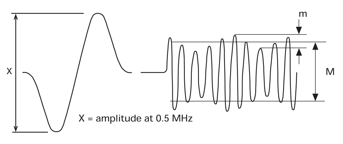
In the - probable - case of a beat affecting camera response for a given spatial frequency, and under certain conditions only, the measured signal reassembles an amplitude-modulated carrier signal, as shown in the following figure:
The percentage of modulation is then defined by the relation:
% mod = M / X
The interference ripple at this frequency is given by:
p % = m / M
This results of the measurement may be presented in the form of a table representing the various areas of the imaging measured.
Lighting
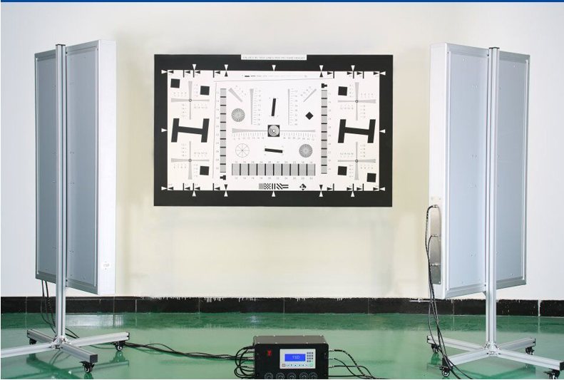
TILO SpectriWave Lighting System TC120-4
Introduction
TILO SpectriWave Lighting System TC120-4 is the latest upgrade product of Shenzhen TILO Standard Light Source Co., Ltd.
Provide professional lighting environment for the camera lens evaluation system.
The operation is simple and convenient, and the light source can be freely switched, the brightness of each light source can be freely adjusted, the dimming is smooth and there is no stroboscopic light, and the usage times and time of each light source are displayed. The inner wall of the light box is equipped with a high-efficiency reflector, and the exterior is equipped with a high light-transmitting diffusing plate, which has high light utilization rate and uniformity.
Product Specifications
Light box dimensions (without bracket, see Figure 1): 1302mm*803mm*100mm
Luminous surface size (see Figure 1): 1187mm*688mm
Control box dimensions (see Figure 2): 370mm * 210.5mm * 227mm
Operating environment: temperature 0-40 °C, relative humidity 80% or less (non-condensing).
Input power: AC220V, 50/60Hz, maximum power consumption 800W.
Net weight (double light box + bracket + control box): 55Kg.
Available lightbox
3nh Transmission Lens assessment light box CC5100/CC3100

Alternative models for DNP light boxes - Brand: 3nh Models: CC5100 and CC3100 Very mature products, illuminance, uniformity, color temperature and dimming performance, can completely replace DNP light boxes.
Product Description
1.Application
Transmission light box provides a special light source for camera test. It can meet the requirements: High-level lighting homogeneity and Continuous Light Intensity Adjustment, etc.
2.Specification
| Model | CC5100/CC3100 |
| Light source: | 5100K(5100K±200k) *4,3100K(3100K±200k) *4 |
| Uniformity: | >95% |
| Luminous Source: | 100 ~ 4400cd/m2 adjustable |
| Illuminance: | 250 ~ 10000Lux adjustable |
| Power supply: | AC230V 50/60HZ |
| Lighting method: | High Frequency lighting method 20KHz |
| Operating temperature: | 10~40℃ |
| Operating humidity: | Below 80%(avoid dew) |
| Major diameter dimension: | 38.5W*34H*15Dcm |
| Luminance plane dimension: | 25W*19Hcm |
3nh Standard LED Transmission Color Viewer HC5100/HC3100
 3nh standard camera color viewer transmission light box is to provide special lighting environment and high illumination uniformity, light continuous adjustable, etc functions. They are
suitable for 4:3 transmission test chart.
HC5100/HC3100 adopts 3nh independent research and development LED light, and it has higher illumination uniformity and better CRI (color rendering index), while CC5100/CC3100 adopts DNP original light and it can get the same color temperature and illumination uniformity with DNP SDCV 3500 transmission light box, but we have 250 ~ 10000 Lux adjustable illuminance while SDCV 3500 only has 6000 ~ 10000 Lux. It can’t meet the requirement who needs to test image quality under 6000 lux.
Transmission light box offers a special light source to check the quality of camera. With two adjusting knobs, we can adjust the illuminance from 0 lux to 11000 lux. It fits for many kinds of transmission test charts 4:3 use, such as transmission greyscale charts, transmissive high resolution test chart, transparency grid test chart, etc. Through image test software, the analysis result is more professional and easier.
Performance Highlights
l Illumination uniformity >92%,Extensive color rendering index CRI>90
l LED dimmable dynamic range 0-11000lx, Flicker Free with 2 dimmer knobs
l Standard Color HC5100/HC3100±100K,Duv ±0.002
l Excellent color/flux stability over 25000 hours lifespan
l 60%+ higher efficiency than fluorescent light tube, Hg Free
General information
l Power supply:AC100-240V,50/60HZ,50W
l Environment required,Temperature10-40℃,<RH80%
l Size:37W*32.5H*16.5Dcm
l Projection area:25W*19Hcm
l Net weight ~6kg
Light measurement
The Japanese 日本 CL-200A chroma meter is suitable for illumination sources, especially some new types of illumination sources, such as light-emitting diode (LED) illumination and organic electroluminescence (Organic EL) illumination. It is used to measure the tristimulus value, chromaticity, chromatic aberration, correlated color temperature and illuminance of the light source. The CL-200A color illuminance meter is used for measurement and adjustment of lighting products, for evaluating the characteristics of light sources, for maintenance of standard light source boxes, for light source research and color detection for projectors, etc.

How the lights should be positioned
The image below summarizes how the lights should be positioned. The goal is even, glare-free illumination. The lamps represent the stacks of three SoLux track lamps, described above. This may involve a tradeoff, especially with wide-angle lenses. Lighting angles between 35 and 45 degrees work well for normal and long lenses. Avoid lighting behind the camera, which can cause glare. Ambient light should be kept subdued. Check carefully for glare and lighting uniformity before you expose, especially with wide angle lenses, where glare can be difficult to avoid: you may have to move the lights further than normal from the target— or allow glare in portions of the target, taking care that it doesn’t affect critical areas.
Use the meter to check for the evenness of lighting. ±20% over the entire target is sufficient for SFR and Distortion measurements, where small portions of the target are analyzed and exposure is not critical. ±5% or better should be the goal for tonal and color measurements (Stepchart, Colorcheck, and Multicharts). This should be easy to achieve because illumination only needs to be even on the relatively small charts themselves, not on the entire target. The widest (the Kodak Q-14) is 14 inches (35 cm) wide; most are under 11 inches (28 cm). Lighting uniformity is strongly affected by the distance and orientation of the lamps. Our lamps are roughly 50 inches (125 cm) from the center of the target.
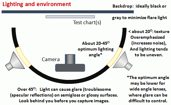
Chart setup
Charts are mounted on 40x60 inch (100x150 cm) or 30x40 inch (75x100 cm) 1/2 inch (1.25 cm) thick foam board, which is lightweight, rigid (unlikely to warp), and easy to find at art supply shops. In some cases, the charts are mounted on neutral, middle gray (-18% reflectance) mat board, which is attached to foam board, to ensure correct exposure in camera phones and webcams with autoexposure.
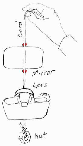
Rope trick (for horizontal positioning)
This trick uses rope and mirrors, as well as the red dots • that mark the horizontal center of the target (or whatever marker you choose).
The cord should be about 1 meter long and have a small weight on one end. A heavy nut— the type that mates with a bolt, not the type that grows on trees— serves well.
Hold the cord in front of the camera (between the camera and mirror), and align your eye and the cord so the so the cord passes in front of the horizontal center markers (red dots • in the images), and so the reflection of the cord passes directly behind the cord. The camera is positioned properly if the center of the lens is aligned with the cord. If it isn’t, shift the camera horizontally until it is.
To complete the horizontal adjustment, rotate (pan) the tripod pan/tilt head so the chart is centered in the image frame.
At this point you should be close enough to correct alignments so the final, fine adjustments should proceed quickly.
Chart
Glare in the outer patches can ruin measurements. With semigloss charts is hard to avoid, even with careful lighting placement. You can reduce it by decreasing the angle between the lights and the chart, but this may make the illumination less even. For this reason matte charts are often recommended when wide angle lenses are being tested (this includes most camera phones).
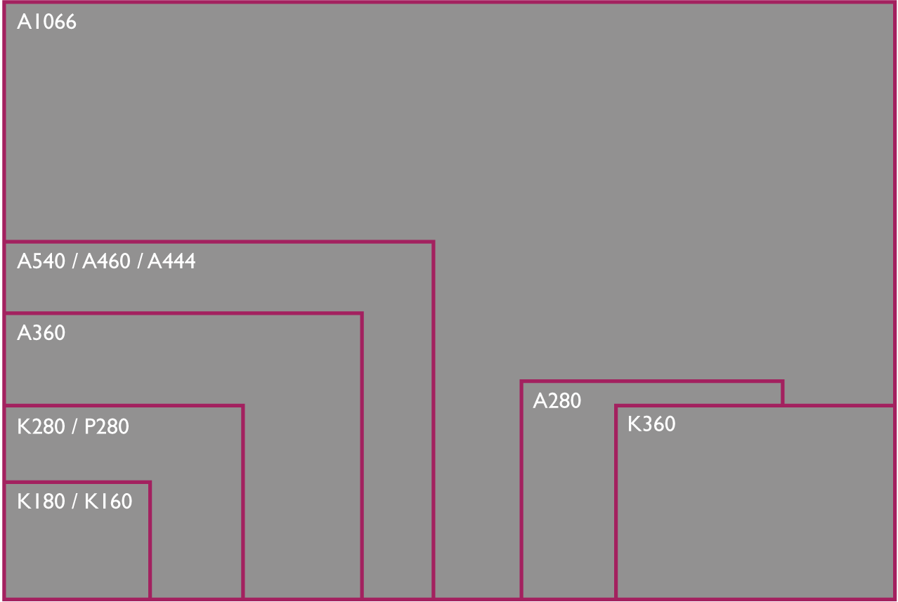
Chart sizes
During production specific regions of test charts are measured to qualify the production process or to additionally create individual reference data acompagnying a test chart. Measured regions can be color or gray tones.
The measurement devices are calibrated regularly and proven before use.
The test charts are available in the sizes listed below. Other size can also be customized, please do not hestitate to ask for additional information.
Reflective
| Picture size WxH (mm) | ||
| 4:3 | 16:9 | |
| A240 | 240x180 | 240*135 |
| A280 | 280x210 | 280x157.5 |
Transmissive
| Picture size WxH (mm) | ||
| 4:3 | 16:9 | |
| D240 | 240x180 | 240*135 |
| D280 | 280x210 | 280x157.5 |

Suitable transmissive charts for the following illuminators
| D240 | D280 |
|
HC5100/HC3100 CC5100/CC3100 |
T259000 high illumination light box |

